| Step | | Procedure & Parts & Tools |
| 1 |
|
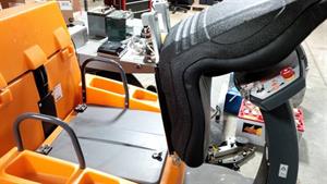
Lift Seat
|
| 2 |
|
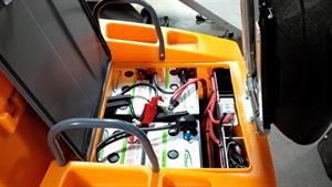
Lift battery cover
|
| 3 |
|
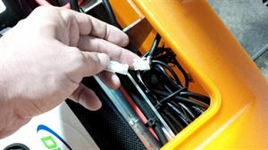
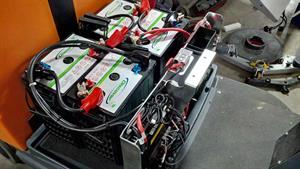
Locate and disconnect seat switch wire IMPORTANT - must disconnect before removing seat or damage will occur.
|
| 4 |
|
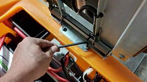
Unbolt two 6MM Allen Head Bolts
| Wrench-Allen metric 6.0mm |
|
|
| 5 |
|
Lift off seat
|
| 6 |
|
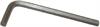
lift orange housing straight up...use assistance if necessary
|
| 7 |
|
Take a scrap of wire and bypass the seat switch. This will allow you to operate the machine without the seat attached.
|
| 8 |
|
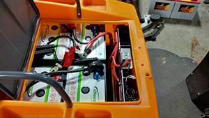
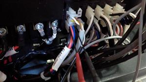
Disable drive by removing Black (negative) Drive Cable from Power Board. Use 4mm Allen Wrench. This will prevent the machine from rolling away while testing.
| Wrench-Allen metric 4.0mm |

|
|
| 9 |
|
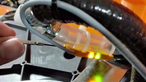
Either have water in tank, or adjust water sensor to show orange and green LED's on a dry hose, turn adjustment screw clockwise until the orange LED lights up. This will allow solution and brush tests to be performed.
|
| 10 |
|
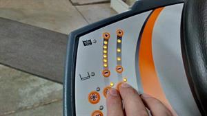
Activate brush and solution system to full settings
|
| 12 |
|
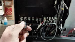
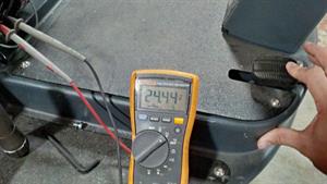
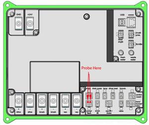
Get out a multimeter (set for Volts DC)...a set of needle or piercing probes may be needed for smaller gauge wires. Using the following diagrams, locate and probe the specified connectors for each function. Failures to produce correct voltage could indicate the need to replace the Power Board.
| Volt meter (True RMS capable) |
&Width=100)
|
|
| 14 |
|
Some Functions require the forward drive to be engaged (Drive, Brush and Solution). Pressing down on the pedal will activate them once the connections are made with the Multimeter...this was why the drive motor was disconnected from the board.
|
| 15 |
|
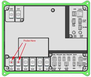
Drive Motor - Probe the connections shown...and depress the pedal. Brush and Solution do not need to be ON. Forward will be approximately -24V (yes, negative), Reverse will be approximately 12V. Turtle Mode will be -17V FWD and 8V REV. If steering wheel is turned all the way left or right, the FWD speed will be -11V.
|
| 16 |
|
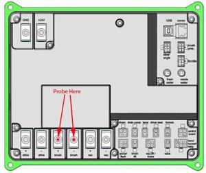
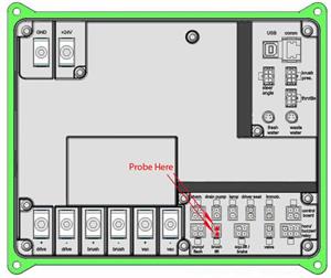
Brush Motor - Probe connections shown...engage brush button on dash and depress pedal. Voltage will be at least 24V
|
| 17 |
|
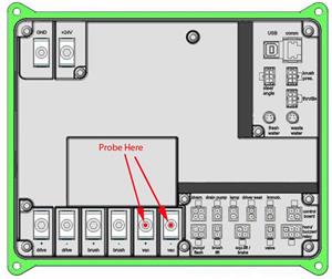
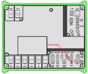
Vac Motor - Probe connections show...engage Vac switch on dash (no need to press pedal). Voltage will be at least 24V in normal mode, and approximately 15-16V in ECO mode.
|
| 18 |
|
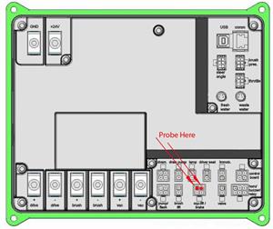
Pump - Probe connections as shown...engage brush and solution to max levels. Depress pedal to engage pump. Max level voltage will be at least 24V...min level will be around 15V. Pump will run a max voltage "prime" for approximately 5 seconds before moving to a lower level.
|
| 19 |
|
Solution Solenoid Valve - Probe connections as shown...engage brush and solution to max levels. Depress pedal to engage Valve. Levels 3-6 will have a max voltage of at least 24V. Levels 1-2 will periodically close the valve, so there will be readings of 0V to 24V+.
|
| 20 |
|
Brush Actuator - Probe connections shown(needle probes will help)...engage brush button on dash and depress pedal. Voltage will be at least -24V(negative) moving downward and at least 24V(positive) moving upward.
|
| 21 |
|
Squeegee Actuator - Probe connections shown(needle probes will help)...engage brush button on dash and depress pedal. Voltage will be at least 24V(Positive) moving downward and at least -24V(negative) moving upward.
|